I designed this printed circuit board (PCB) to allow regular 2732 through 27256 EPROM chips to be plugged into the cartridge expansion port of a TRS-80 Color Computer. My main motivation was to crank out a simple design to try out a prototype PCB vendor called OSH Park. Unlike most small-run, online-ordered PCB vendors, they provide boards with ENIG (gold plating) surface finish, which is much better than HASL (solder plating) for edge connectors.
Here is the schematic diagram:
I have released all of the Eagle PCB design files under GPLv3, and they are available on GitLab:
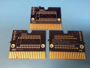
Here are some pictures of the bare boards:
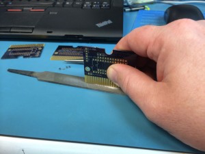
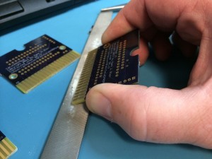
When the bare PCBs arrived from OSH Park, they still had remnants of the panelization tabs present. Those easily snap off with pliers, leaving “rat bites” behind. The rat bites on the edge with the card edge contact fingers should be filed off for proper insertion into the card edge connector. The rat bites on the other edges can be left alone or filed off as desired.
The edge with the card edge contact fingers should also be lightly beveled on both sides for smooth insertion into the connector.
The PCB fits properly in the housing from an old Color Scripsit program pak.
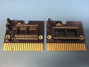
Here are two of them assembled; one each with the two different socket options, so that I can test all of the EPROM sizes that the board is supposed to support.
I have tested the boards with 2732 (4k), 2764 (8k), 27128 (16k) and 27256 (two banks of 16k each) EPROMs. The board should also support 27512 (four banks of 16k each) EPROMs, but I don’t have any handy to test at this time.
The OSH Park site has a feature called Shared Projects, which is ideal for sharing open-source PCB designs. It lets anybody order bare PCBs for the shared projects from OSH Park directly. I have made CoCoEPROMpak boards available here:
I don’t make any money off of this. If you order PCBs from OSH Park, I won’t be involved and I won’t make a penny. But if you do order them, please feel free to comment below. Please follow that link for updated pricing. When I ordered my samples, I got three boards for just under $20 including shipping.
To use the boards, you’ll need to solder on a DIP socket, a 0.1uF capacitor, and a few jumpers. You might like to wire the bank select jumpers to switches mounted in the edge of an old Program Pak housing so that you can easily switch banks when using larger EPROMs. You’ll need to decide whether you want to use an 2732 EPROM or one of the larger ones, so that you can install the correct socket. Only one socket or the other may be installed, depending on whether you will use a 2732 (24 pins) or a 2764-27512 (28 pins).
Ok, time for some disclaimers: This project is pretty much unsupported, and I’ve made it available in hope that it may be useful to moderately experienced electronics hobbyists. Please study the schematic diagram carefully and understand it fully before you try this out.
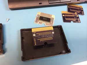
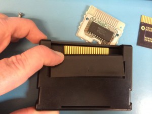
Thinking of installing some micro-switches on the cartridge case… good thing I have some of those boring “educational” cartridges lying around.
I ordered the Color Scripsit cartridge off eBay specifically to take it apart and measure the plastics to make a CAD model (which I haven’t gotten around to doing yet). I picked it because it was the cheapest one on eBay at the moment. Once I ran it, I could see why they’re so cheap… that screen color scheme is AWFUL!
The configuration and bank select connections are set up for regular 0.1 inch pitch header pins. You can solder in wire jumpers, use header pins and shunt blocks, solder in wires for remote switches, etc. I also put a jumper across the connection that normally tells the CoCo to auto-boot the cartridge. That way, if you want to map an EPROM but not jump into it at power-on for any reason, you don’t need to cut a trace or tape over a pin. Many folks might just solder across that jumper with a piece of wire.
Hi Mark:
I have a couple of the CoCo computers and like them. See:
http://www.prc68.com/I/comp.shtml#CoCo
Did you know that the op sys is stored in ROM, but at power up is transferred into RAM? That means you can load any op system such as OS9. You can also change the base address of the display data and so display code on the TV set. There is a display adapter cartridge to allow 80 character lines.
Have Fun,
Brooke, N6GCE
http://www.PRC68.com
Color Computers were sold with as little as 4k of RAM, with 8k or 16k of ROM for Color Basic or Extended Color Basic, respectively. A plugged in cartridge could add up to 16k bytes, minus 256 bytes of control registers overlaid from FF00 through FFFF. Most cartridge ROMs were 4k or 8k.
While the CoCo 3 could have up to 512k of RAM and had some bank-switching capability, the CoCo and CoCo2 were normally limited to 64k or less of RAM. 64k CoCo/CoCo2 machines could map RAM in the upper 32k of address space instead of ROM, but 32k and smaller machines could not do that.
Copying non-position-independent ROM code into RAM for execution was possible in the 64k machines, but not in the 4k through 32k machines. On the 64k machines, a SAM control register at FFDE/FFDF allowed the upper 32k of the address space to be mapped to the upper 32k of RAM instead of the ROMs that were normally mapped there. ROM code was normally just executed out of ROM, since a lot of the CoCos had 32k or less RAM and thus had no ability to map RAM in place of the ROMs.
My first computer was a Color Computer with 16k of RAM. My dad upgraded it to 64k later. It was one of the original silver ones with the awful “chiclet” keyboard. I don’t have that machine any more, but now I have a 64k CoCo 2 (on my trade list!), and a CoCo 3 that came with 128k but I’ve upgraded it to 512k. I’ve just gotten into retrocomputing very recently, but I’ve hit the acquisition phase really hard!
Let me add a correction to my previous comment: The CoCo 3, unlike the CoCo 1 or 2, did copy its ROM to RAM at boot time and then patch the RAM copy, according to this great book I just read about the history of the CoCo. The reason for this unusual action instead of simply executing the code out of ROM was apparently because Microsoft didn’t want to get on board to create the new Extended Color Basic 2.0 for the CoCo 3. Tandy took the approach of including unmodified Extended Color Basic code from the CoCo 2 in the CoCo 3’s ROMs, and then patching the binary at boot time to hook in the new CoCo 3 features. The contracted Microware Systems Corp. to make the new Extended Color Basic 2.0 in this manner. It’s said that certain execs at Tandy nearly blew a gasket when they learned about the easter egg that Microware slipped into the new ROMs, and nearly cancelled the CoCo3 project over it. Some folks are wound up way too tight.
Hi Mark, thanks very much for making your boards available.
I just received a batch of 3 from OSH Park yesterday 22nd January 2014 (ordered on the 5th January).
They look great.
Cheers,
Shane.
Melbourne, Australia.
Thanks!
There’s also another guy who has tweaked the design a bit, and he’s put a few up for sale on eBay off and on.
Would any modifications need to be made to use this board to use EEPROMs like 29C256?
I haven’t used 29Cxxx EEPROMs before. I dug up a datasheet for one, and it looks like they should be usable on the CoCoEPROMpak as read-only memory without any modifications. CoCoEPROMpak doesn’t support writing to them, though, so the chip would still need to be programmed in an external programmer before plugging it into the CoCoEPROMpak socket.
Of course, I didn’t expect to write to them on the CoCo itself! But that’s good to know. I’ve ordered some boards, so I’ll be sure to let you know how it goes when they arrive. Cheers for the quick response too! :-D
Cool! I hope they work well!
Hi Mark,
I just ordered a batch of your CoCo EPROM boards through the OSH Park Shared Project.
This is an excellent way to share things like this. Thank you very much for your effort, and for your thoughtfulness to the CoCo community.
I purchased a relatively unknown CoCo game cartridge on eBay, and I’ve successfully gotten the label off and cleaned it all up and I have it disassembled and ready to go for when my boards arrive.
I’m figuring that I would like to put a DriveWire 3/4 HDB-DOS EPROM (available from http://www.cloud9tech.com) in my first cartridge, so I can be up and running with Drivewire without having to load the HDB-DOS from cassette (a PC .WAV file) every time. Beyond that, I don’t know right now.
smp
So far, I have been using HDBDOS on my first CoCo EPROM board, mounted in a vintage CoCo cartridge case (thank you, Seller on eBay, for posting the obscure game cartridge for $3.95 and free shipping!).
Just this past week, I assembled a second CoCo EPROM board to hold a copy of an old cartridge that is not available anywhere, but I found the raw cartridge dump online. Works perfectly!
That’s two down and one left to go. Thanks a million, Mark, for your most excellent effort on this. I don’t know if I ever made better use of $18 and change on any hobby project!
smp
Just ordered a batch! I have been wanting to try some of the interfacing projects in “A Full Turn of the Screw” for some time. That and make an EDTASM+ cart. These should simplify things greatly for me.
Thanks for doing this!
You are very welcome! Good luck with your projects!
I’m @nf6x on Twitter.
Hi Mark,
Just received a set of boards and the look great. I have already programmed 27C128 eproms for my Coco 2 & 3 for HDBDOS
Hooray!
Hi,
Is there the EagleCAD library available for the cartridge pinout part? The GitHub does not have the .lbr file for the cartridge pinout. Thanks!
I just exported a .lbr of all of the components used in the design. I don’t use Eagle any more, but luckily I still have it installed on my computer. Good luck, and I hope you make some cool stuff!
Dud! Somehow I missed it on the Git site. It’s there. https://github.com/NF6X/CoCoEPROMpak/blob/master/CoCoEPROMpak.lbr!
Thanks for great work! Will have fun with this project!
You didn’t miss anything… it didn’t exist a few minutes ago!
Well, eaglecad software 7.7 (latest version) does not read the *.sch/*.brd or the .lbr unfortunately.
What version of eaglecad did you use for your project? Is there a way to make the .sch/.brd/.lbr readable on the some later versions of eaglecad?
Thanks!
I think I created the .sch and .brd with 6.4, and I just created the .lbr now with 6.6. I quit using Eagle and moved to KiCad back at Eagle version 6.6, so I don’t know anything about newer versions of Eagle.
Thanks, Mark! Works great! Your files should work with the latest EagleCAD. My bad that I downloaded the .lbr/.sch as HTML :-)
Btw, ftp://ftp.cadsoft.de/eagle/program/ is where to download older versions of EagleCAD. But Mark’s .sch/.brd/.lbr should be fine with the latest EagleCAD 7.7.0 release of today. I tested it out!
Thanks, again for this great project. Finally, I can do something with my Coco2 :-)
Hey Mark,
I do have one question. Hope you don’t mind. In the case of using a 32KB EEPROM, which means that it will cover the address range of 0x8000 to 0xFF00, according to the Coco2’s memory map. However, the Coco2’s BASIC ROM is from 0xA000 to 0xC000, which is within the 32KB EEPROM range.
So, if I have a 32KB ROM, the Coco2 just executes my code in the 32KB ROM as a cartridge, and there won’t be BASIC? Is that why in the schematic you tied the Q and /CART signals together?
Thanks!
The EPROM is always mapped to an almost-16k window from 0xC000-0xFEFF. When you install a 32k EPROM on this board, you select whether the lower or upper half of the EPROM is used with jumper JP2. If you install a 64k EPROM, then you select which quarter of it is accessible with jumpers JP2 and JP3. In any case, the BASIC ROM is still present at its normal address range; it just doesn’t get executed at reset time when a Program Pak is installed.
Tying Q and /CART together is necessary for any normal Program Pak ROM. This is what forces the CoCo to jump into the EPROM code instead of launching BASIC as usual. Jumper JP1 can be removed for things like Disk BASIC ROMs, which extend BASIC rather than executing instead of it.
Mark’s design makes it easy to see how addressing is performed for selection of the 16K bank via the A14 address line. If you took one of his standard boards and installed a jumper wire from the A14 pin underneath the chip socket to the A14 line of the card edge connecter while leaving the banking jumper OFF, you would have a 32K board. By tying these chip lines to the card edge connector, you are allowing the CoCo to select the upper 16K or lower 16K dynamically.
I wanted to use a 2716 with your board (2k EPROM) because the Tandy Diagnostics Cartridge 2.0 is only 2k long. Will that work, or should I buy some 2732s?
A 2716 will not work without modifying the board, because the 2716 needs a +5V power supply on its Vpp pin, but that pin would be connected to address line A11 on this board. The only EPROMs this board was designed to accept are 2732, 2764, 27128, 27256, and 27512. You could either use one of those EPROMs, or you could do some surgery on the board… I think it would be easier to use a supported EPROM.
I had a feeling. But, just wanted it confirmed. Thanks!
Hi Mark,
I dropped by to your site looking for details of how to convert .ccc files to .bin files for burning to an EEPROM. I made my first CoCo cart using your board design a year or so ago now. The only one I wanted at the time was the Divewire ROM.
Now, I’m wanting to make a few game carts and I’m looking at how to convert the files, and also whether I can use switches to select between 1 of 4 16K games from a 64K EEPROM.
Anyway, thanks for putting your board design into the public domain. I enjoy making carts for my old computers, as buying second hand ones is getting prohibitively expensive.
Cheers,
Mike
Hi! I don’t think there’s any difference between a .ccc file vs. a plain .bin file other than the filename. Yes, you can use switches to select four 16k banks from a 64k EEPROM. Use SPDT switches connected to JP2 and JP3. You’ll need to figure out how to burn your four ROM files at the correct offsets (16384 byte boundaries) in the EEPROM.