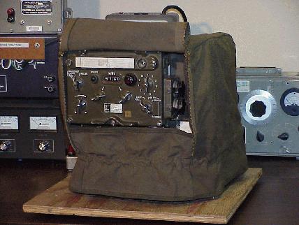
Please note that I do not have any original manuals for this set, and I do not even have a complete set of copied manuals (for example, I do not have any aligment procedures, and I would have great difficulty understanding them even if I had them due to my very poor command of the German language). I cannot provide any further information beyond what is described here at this time, and I cannot provide manual photocopies or other printed information at this time. This page truly contains everything I know about the SEM-25!
Please comment me if you discover any errors in this paper.
I hope you find this information useful!
Description
The SEM-25 is a West German short-range tactical vehicular VHF FM transceiver which was introduced in the 1960’s, and was apparently used until at least the 1980’s. Although surplus SEM-25 radios are not yet very common in the U.S., some have recently appeared on the U.S. surplus market from vendors such as Murphy’s Surplus Warehouse.
The SEM-25 covers 26.00 to 69.95 MHz, in 50 kHz steps. It is all solid-state, except for three tubes in the transmitter power amplifier. A SEM-25 system will typically consist of at least the following items:
- Transceiver chassis
- Control box (may be mounted on front of transceiver, or remotely)
- Mounting/power supply
- Power transient suppressor
- Antenna tuning unit
- Antenna
- Audio accessories ranging from a simple handset to several junction boxes and headsets
- Various cables
More complicated systems may consist of two SEM-25 transceivers and one EM-25 receiver, with lots of audio gear and cabling, thus providing a set with retransmission and intercom features.
So far, I have only obtained a transceiver chassis, control box and mounting, so I cannot provide much information about the antenna, antenna tuning unit, power surge protector or other accessories at this time. The audio connections on the control box and main chassis are compatible with common 1950’s U.S. audio accessories such as the H-33/PT handset and LS-166/U loudspeaker. Pictures I have seen of the correct German audio accessories (well, actually photocopied photocopied photocopies…) suggest that the correct German handset (called an H-33G) appears virtually identical to its U.S. counterpart, and the correct loudspeaker has a case like a U.S. LS-7 loudspeaker with a mounting like a U.S. LS-166. The headset looks a lot like a U.S. H-63/U with an AN/GSA-6 control box. The antenna whip elements are called MS118AK, MS117A and MS116A, and look very similar to U.S. elements with similar names, and the antenna base looks a lot like the U.S. MP-65. The knobs on the control box look just like 1950’s U.S. knobs. I’m really surprised at the similarities between this set and comparable U.S. sets, in spite of the fact that they were designed and built in different countries.
I first learned of the existence of the SEM-25 when I saw a pile of them on the shelves in the famous back room of Murphy’s shop in late 1998. Although I had never been very interested in foreign military gear before, the SEM-25 looked like a neat radio, so I talked my folks into getting me one for Christmas in 1998. My dad and I made the hour-long drive down to Murphy’s shop on Christmas Eve, and I picked out the nicest-looking radio from the pile. It was even gift-wrapped in a stylish olive drab canvas cover!
At the time, Mike was charging $350 for the SEM-25, and $250 for a smaller but similar-looking radio which he called a “SEM-20”. The smaller radio is actually an EM-25 receiver; it’s basically a receive-only version of the SEM-25. It’s easy to get confused about the features and identification of these two radios, because they both use the same control box and share many modules, so the EM-25 is prone to have stickers which say “SEM-25” (or even “SEM-35”; it shares two internal modules with the SEM-35 backpack transceiver) on and inside it, and it will have controls for transmitting functions which it does not perform.
The “SEM” in “SEM-25” is short for “Sender-Empfangsgerät”, which is German for “transmitter-receiver”. Similarly, the “EM” in “EM-25” is short for “Empfangsgerät”, which is German for “receiver”.
Specifications
General
| Modes | Simplex, retransmit |
|---|---|
| Frequency range | 26.00-69.95 MHz |
| Channel spacing | 50 kHz |
| Number of channels | 880 |
| Channel selection | 44 1-MHz bands, 20 50-kHz channels each |
| Programmable channels | 10 |
| Modulation | FM |
| Operation, including frequency selection | Operated from a transceiver-mounted control box, or from a relocatable control box in vehicle (max. cable length 10m) |
| Transmitter operation |
|
| Remote input and output arrangement | From telephone remote control over field phone wires, up to 3 km long, max. resistance 480 ohms |
| Temperature range | Operating range from -45°C to +60°C |
| Overvoltage protector | For transients up to 65V from the battery regulator |
| Power supply | 24V battery supply, negative ground, permissible voltage range 21V to 29V, short term overvoltage up to 32V |
Transmitter
| Output power | High: 15 W Low: approx. 1 W |
|---|---|
| Calling frequency | 1600 Hz |
| Audio input |
|
| Warm-up time | approx. 30 seconds |
Receiver
| Sensitivity | <= 0.5 µV for 20 dB s/n with 1000 Hz modulation and 10.5 kHz deviation |
|---|---|
| Bandwidth | >= 30 kHz at 6 dB points |
| Selectivity | +/- 50 kHz at 80 dB points |
| Audio output |
|
Power Supply
| Voltage | 24V battery (21V to 29V), negative ground, permissible short term overvoltage up to 32V |
|---|---|
| Power requirements, RX | approx. 10 W |
| Power requirements, TX Low | approx. 50 W while transmitting |
| Power requirements, TX High | approx. 80 W while transmitting |
| Power requirements, TX Low or TX High | approx. 29 W when not transmitting |
Sizes and Weights
| Item | Height (mm) | Width (mm) | Depth (mm) | Weight (kg) |
|---|---|---|---|---|
| Control box | 174 | 228 | 75.5 | 2.54 |
| Transceiver | 222 | 268 | 255 | 14.59 |
| Transceiver mount | 120 | 320 | 300 | 9.43 |
| Receiver | 222 | 196 | 255 | 11.08 |
| Receiver mount | 120 | 320 | 230 | 6.68 |
| Antenna tuning unit | 122 | 290 | 110 | 3.70 |
| Overvoltage protector | 93 | 250 | 126 | 2.62 |
| Spares case | 48 | 140 | 140 | 0.73 |
Controls
This section decribes the functions of the controls on the SEM-25 control box.
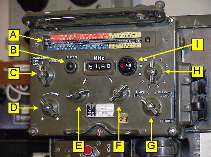
| Ref. | Description |
|---|---|
| A | Channel programming drum (behind cover) |
| B | Call button: Keys transmitter, sends 1600 Hz tone |
| C | Squelch |
| D | Volume |
| E | Manual tuning, 1 MHz steps |
| F | Manual tuning, 50 kHz steps |
| G | Power |
| H | Channel selector (H = manual tuning) |
| I | Power-on light (turn bezel to dim) |
Power Switch Settings (Ref. G)
| AUS: | Off |
|---|---|
| EMPF: | Receive-only |
| SENDEN KLEIN: | Transmit/receive (low power) |
| SENDEN GROSS: | Transmit/receive (high power) |
Squelch Switch Settings (Ref. C)
Note: Squelch is opened by carrier level, equivalent to “old” mode in U.S. radios.
| RAUSCHSP. AUS: | Squelch off |
|---|---|
| RAUSCHSP. EIN: | Squelch on |
| RELAIS: | Relay (retransmit) |
Connectors
This section describes the functions of the external connectors on the SEM-25.
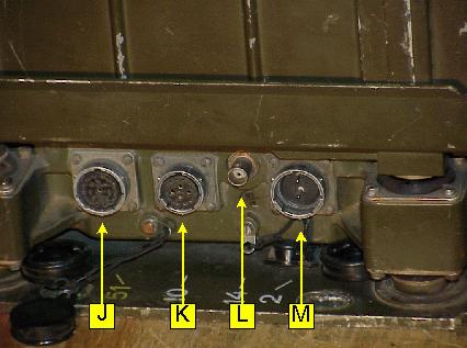
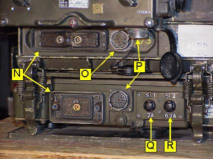
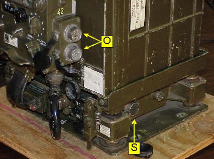
| Ref. | Description |
|---|---|
| J | From transceiver #1 in multi-radio sets |
| K | Antenna tuner control |
| L | Antenna RF |
| M | Power input |
| N | Mounting/transceiver interconnect |
| O | Audio |
| P | Control box/mounting interconnect |
| Q | Receiver fuse (2A) |
| R | Transmitter fuse (6.3A) |
| S | To transceiver #2 or aux. receiver in multi-radio sets |
Modules
This section identifies the SEM-25’s major internal modules. Note that two of the modules (as noted below) are also used in the SEM-35 backpack/vehicular transceiver.
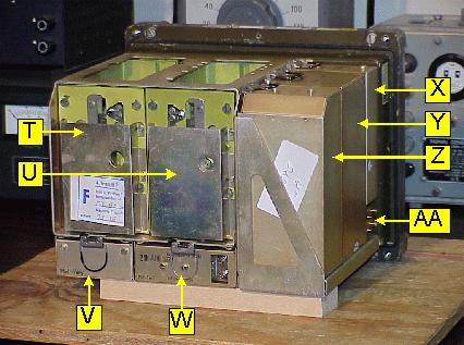
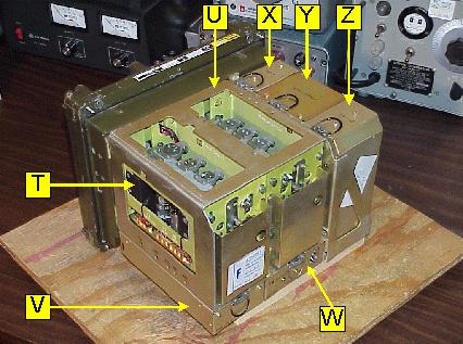
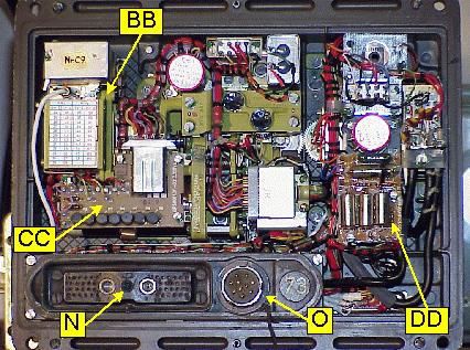
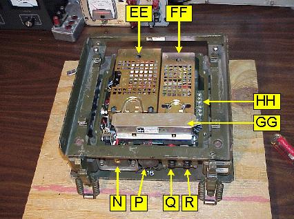
| Ref. | Description |
|---|---|
| N | Mounting/transceiver interconnect (external) |
| O | Audio connector (external) |
| P | Control box/mounting interconnect (external) |
| Q | Receiver fuse (2A) (external) |
| R | Transmitter fuse (6.3A) (external) |
| T | Transmitter RF |
| U | Receiver RF |
| V | Modulator amplifier, 1600 Hz tone generator, and 11.5 MHz discriminator for automatic frequency control (AFC) of transmitter |
| W | Audio amplifier |
| X | Receiver power supply and control amplifier |
| Y | Frequency synthesizer (also used in SEM-35) |
| Z | IF (Intermediate Frequency) module (also used in SEM-35) |
| AA | Plugs for test box |
| BB | 10-frequency crystal oscillator |
| CC | Receiver servo |
| DD | Transmitter servo |
| EE | Transmitter power supply |
| FF | Motor drive power supply for external antenna tuner |
| GG | Relays for interconnect of multiple transceivers |
| HH | 600 ohm balanced audio connections |
Internal Adjustments
While we have the case open, here are some of the major internal adjustments:
| Control | Label | Location | Function |
|---|---|---|---|
| R36 | Rauschperre | Audio amp. (Ref. W) | Squelch level |
| R5 | NF-Pegel | Audio amp. (Ref. W) | Audio level |
| R13 | Eing. | Mod. amp. (Ref. V) | Mod. amp. input gain |
| R26 | Ausg. | Mod. amp. (Ref. V) | Mod. amp. output gain |
| R38 | Tacho | Rx power supply (Ref. X) | Stepping speed trim (?) |
Schematics
The diagrams in this section were scanned at 150 pixels per inch, and you will probably need to use an external graphics-editing program to print them (simply clicking your browser’s “Print” button probably won’t work well).
The diagrams were all scanned from photocopied manuals, and the originals are just as blurry as the scans, so don’t bother asking for photocopies of the schematics! :-)
Block Diagrams
| Description | File | Size |
|---|---|---|
| Transceiver | blk01.gif | 1100×1338, 33k |
| Frequency selection | blk02.gif | 1100×1540, 44k |
| Receiver | blk03.gif | 1172×946, 20k |
| Transmitter | blk04.gif | 1082×888, 12k |
| Antenna tuner (external) | blk05.gif | 948×1240, 15k |
Schematic Diagrams
The “Ref.” column shows the corresponding reference letters from the module identification pictures (where applicable), to help you figure out which part of the radio is described by each schematic.
| Description | Ref. | File | Size |
|---|---|---|---|
| Wiring (main chassis) | — | sch01.gif | 1744×1232, 90k |
| Transmitter RF | T | sch02.gif | 1744×1232, 70k |
| Receiver RF | U | sch03.gif | 1744×1232, 70k |
| Modulator amplifier module | V | sch04.gif | 1744×1232, 62k |
| Audio amplifier module | W | sch05.gif | 1744×1232, 55k |
| Receiver power supply module | X | sch06.gif | 1744×1232, 66k |
| Frequency synthesizer module | Y | sch07.gif | 2381×1231, 117k |
| IF module | Z | sch08.gif | 2539×1232, 84k |
| 10-freq. crystal oscillator | BB | sch09.gif | 1193×768, 17k |
| Receiver servo | CC | sch10.gif | 1196×778, 38k |
| Transmitter servo | DD | sch11.gif | 1172×809, 19k |
| Control box | — | sch12.gif | 3042×1226, 104k |
| Wiring (mounting) | — | sch13.gif | 1744×1232, 94k |
| Transmitter power supply | EE | sch14.gif | 778×1159, 36k |
| Motor drive power supply | FF | sch15.gif | 1187×772, 26k |
| Interconnect relays | GG | sch16.gif | 1197×794, 36k |
| Transient protector (external) | — | sch17.gif | 1201×790, 34k |
| Antenna tuner (external) | — | sch18.gif | 1744×1232, 68k |
English/German Translations
This section lists rough translations of some German words, phrases and abbreviations as used in the SEM-25’s schematics, module labels, etc. My command of German is very poor, so there may be mistakes here… please comment if you can correct any of my translations!
- Abstimmgerät
- Radio tuner (tune + apparatus)
- Abstimmteil
- Radio tuner section (tune + part)
- Additionsstufe
- Addition stage
- Anschluß
- Connection
- Antennen
- Antennas
- Antrieb
- Drive, driver, motor
- Ausgang
- Output
- Bausteinträger
- Component carrier
- Bauteile
- Components
- Bedien
- Control head
- Begrenzer
- Limiter
- Blockschaltbild
- Block diagram
- Bordbatterie
- On-board battery
- Bordverstärker
- Intercom (on-board + amplifier)
- Diskriminator
- Discriminator
- Eingang
- Input
- Einsatz
- Part, component
- Empf.
- Receive or receiver
- Empfänger
- Receiver
- Endstufe
- Output stage
- erdfrei
- Balanced (i.e. “balanced line”; literally, “ground-free”)
- Frequenzaufbereitung
- Frequency synthesizer
- Funk
- Radio
- geschlossen
- Closed
- gezeichnet
- Drawn
- gross
- Large
- Grundplatte
- Mounting (base + plate)
- HF
- Radio frequency (RF)
- Hinweis
- Note
- im
- In
- Kanalwahl
- Channel selection
- klein
- Small
- Leitung
- Line, wire
- Ltg.
- Line, wire
- Masse
- Common, ground
- Mischstufe
- Mixer
- Netzgerät
- Mains power adapter
- NF
- Audio frequency
- Oberton
- Overtone
- offen
- Open
- Oszillator
- Oscillator
- Prüfgerät
- Test meter
- quarz
- Quartz
- rauschperre
- Squelch (noise + stop)
- relais
- Relay, retransmit
- rufen
- Call
- ruhezustand
- Off-state
- senden
- Transmit
- Sender
- Transmitter
- Servoverstärker
- Servo amplifier
- Steuerverstärker
- Servo amplifier
- Stromversorgung
- Power supply
- Teil
- Part
- Transientschutz
- Transient protector
- Treibertufe
- Driver stage
- Trennstufe
- Divider stage
- Umwandler
- Converter
- Verstärker
- Amplifier
- Vorstufe
- Input stage
- ZF
- Intermediate frequency (IF)
Credits
This work would not have been possible without the generous assistance of the following people:
Pictures were taken with a Sony MVC-FD91 digital camera. Reference letters were added with Visio 4 on a Windows NT box; all other image editing was performed with xv and gimp on a Redhat Linux system.
Scanned documents were scanned with a Umax Astra 1220S scanner and the SANE software under Redhat Linux, and then edited with xv and gimp.
You have a very nice info site for the SEM-25! Thanks for your efforts. I have a couple of SEM-25’s and a couple of SEM-35’s, and a Unimog radio truck in which they were original equipment.
One remaining mystery for me is how the antenna tuner knows when there is a match with the radio channel. Any thoughts?
73,
Bob WB4ETT
Thank you!
I have not actually connected my antenna tuner to my SEM-25 yet… they’re sitting in various piles in the garage until I get around to playing with them again. That being said, I think that the tuner works about the same way as the MX-6707 tuner for the AN/VRC-12 series radios: It’s not an automatic antenna tuner that tunes until it finds a match. Instead, internal adjustments define the matching network to be used for each range of frequencies, assuming that the standard whip is installed. The radio tells the tuner which frequency range it’s in, and then the tuner selects the fixed matching network for that range. If the tuner is out of adjustment, or a nonstandard whip is installed, or possibly even if the antenna is installed in an unusual way, then the tuner will happily and blindly adjust to a poor match.
Correct Mark! There is a specific measurement box which contains an SWR meter, a dummy load and (most important) three special tuning tools, where you need two to comfortably ajust the Antenna tuner for each 1 MHz step. Just set the radio to XX.50 MHz, open up the two screws on top of the ATU, srew in the special tools and adjust for that frequency point for minimum SWR while transmitting. What is interesting to me is that there is a diode detector in the ATU to measure the voltage at the antenna, which is neither used by the SEM25 nor the measurement box.
73
Gregor, OE1GLC
HELLO, I AM AN ITALIAN AMATEUR, PLEASE HELP ME FOR SOME ADJUSTMENTS SEM 25?
I WOULD LIKE TO KNOW MORE JUST WHAT ARE THE SETTINGS ABOVE: R 36, R5, R13, R26.
I WOULD LIKE TO KNOW EVEN IF YOU CAN ADJUST IN 25 SEM MIC GAIN, RF GAIN, AND THE DIVERSION FM. THANK YOU ANSWER YOUR APPEARANCE.
Hi! I have never changed any of the internal adjustments in my SEM-25. I wrote this page about 15 years ago, so my memory may be wrong, but I think that my list of those settings is just a translation of the German markings that I found inside the radio into English. I would guess that R13 and/or R26 might affect the mic gain? I don’t know how to adjust the deviation, or if there is an adjustment for that.
Maybe somebody who knows more about adjusting the SEM-25 will see this and reply with better information?
I am sorry that I’m can’t be more helpful right now. Good luck!
I just looked at the modulator amplifier module schematic, and I would guess that R13 is probably a microphone gain adjustment. If you experiment with any of the settings, make sure that you note the original settings before you change anything!
thanks for response mark, 73 !!! hear from you soon
Hi, looking in the manual it seems like ther is a Audio limiter adjustment (R26) in the modulation amplifier, and the Audio amplifier adjustment R13. According to the manual, R26 is adjusted at 1,25V (effective?) sinewave input at 1kHz for 15kHz maximum FM deviation. Prior to this, R13 is adjusted for 10,5 kHz deviation at 250mV input level, again for 1kHz.
I assume you want to reduce the FM deviation for Ham use, so you may pick lower deviation values. But keep in mind, that for RX the SEM is still designed for rather broadband FM.
R36 is the squech setting, I guess setup is selfexplanatory. R5 just sets the audio level for received audio, I guess this is important when all the audio tank communication acessories are used.
73 de Gregor, OE1GLC
Thanks for posting that! It should be very helpful!
Sorry for my English…
I have the German version of the LS-166/U and, at least on the earlier versions it seems to contain exactly the same internal parts as the US one (even the speaker elements etc seems to hawe been made in United States. ) , in fact i think it IS the same and possibly even made in US, only differense i can point my finger on is for example that the text abowe the switch is written in German language instead of US (but even parts of the text is the same for example; Lautsprächer-Loudspeaker =LS in both languages osv… So even the military name will be exactly the same as in US in written form. ). The specifications also seems to be the same: 8/600 Ohm osv. Later version (at least the one i hawe) seems to contain a bit more modern parts, i dont know if the speaker elements in later wersions are still made in UnitedStates or if they are made in Germany. But the specifications are still the same as US standard here, 600/5 Ohm (it seems like it has changet from 8 to 5 ohm in the direct mode with later speaker elements (however, that one not the old U model so it´s possible other reasons why the internal resistans differs slightly in the specifications)). The old version i hawe has internal speaker element made by Academy but the later one i hawe is made by A. S. C.
Hi SEM25 community!
Is there anyone out there who ever tried to remove the transmitter module (“T” in the above picture) from the “Bausteinträger” (main chassis)? I just wonder if I have to remove the transmit servo first, and how difficult it is to achieve the synchronization afterwards. I tried to loosen the 5 screws holding the transmitter module but the thing did not really move.
(My current project SEM has a broken trimmer capacitor C47, so the lowband TX does not work. The initial fault may have caused some military repair technician to “tweak” all TX trimmers before giving up on that project, and he obviously destroyed C47 on that job..)
Regards, 73
Gregor
OE1GLC
It has been a very long time since I have opened up my SEM-25, but I don’t think that I have removed that module. I don’t think that the “T” or “U” modules pop out easily like the other modules. I hope that somebody with more experience will post a reply.
Congratulations on your page.
I have in my collection a German SEM-25 radio, which is now working.
Got it repaired using schematic diagrams of your page.
Thank you for providing the schematics.
Forte 73 PY3CE of Brazil.
I’m really happy to hear that the diagrams were helpful!
Mark i reve a service maual for SEM-25 in german in digital pdf.
You an a copy ?i sendi one copy four you an e-mail.
Yes, I could use that manual. Thank you!
Good night Mark.
This is the link you can access to download directly from the web, the service manual SEM-25 Radio.
http://www.radiomanual.info/schemi/Surplus_NATO/SEM-25_TDv_5820_045-12.pdf
73 PY3CE
Thank you very much!
Hello from Germany !
Very interesting site !!! Many thanks and congratulations !!!
Unfortunately it is very difficult to get the technical manual about the sem 25 (and others). The only manual I have is the common description of the set. Much of the things about the sem 25 I know today I learned in the army many years ago, where we used this radios, and circuit diagrams I’ve got from a ham I met at the HAM-Radio in Friedrichshafen. There are some parts in the radio which can be changed very easy (for example the plug-in modules and the tubes), and others which were made for never to be touched (for example the tuning section), in which are so many mechanical parts that it will be a problem to put them together when they’re removed….so that it works.
If somebody of you can buy a Transmitter-Receiver-Testset (Sendeempfänger-Prüfgerät “SEP SEM 25”), USE THIS OCASSION !!! It makes it much easier to locate Problems or to adjust the radio.
73,
Klaus, DL4FCY
Mark I have a problem in my SEM25 only transmits on frequencies below 46.95 MHZ you know what can star going on?
These frequencies normally but transmits in frequencies above 46.95 does not transmit.
Thank you for your attention
Hello Cristiano !
Many times ago I had the same problem, but it was very easy to fix (in my case):
In the Control Box ( Funk-Bediengerät) is a switch that switches between the lower band (26,00 – 46MHz) OPEN and the upper band (47-69 MHz) CLOSED. I hope you have a schematic diagram-it is S2 near the MHz-Switch. If the switch is not correctly mechanicly adjusted, it doesn’t switch if you change between the upper and the lower band , so that you can only use either the upper band or the lower band-depending if the switch is OPEN or CLOSED. In your radio the switch should be CLOSED so that only the upper band can be used. You can find the switch very easy in the opened Control box. If the switch is damaged, it can be changed easy, because the type of switch is a “normal” type.
I hope this will help to make your SEM 25 work!
73,
Klaus, DL4FCY
Thank you for responding, Klaus! I did not know how to help Cristiano, because I have not done any repairs on my SEM-25 yet.
Hey Christiano,
if the suggestion from Klaus does not fix the problem, be aware that the transmitter uses mostly separate tuned circuits for the upper and lower band. there is a big motorized switch in the transmitter compartment, which does handle these two bands. Take a look at the switch first: If zou toggle between upper and lower band, do all switch wavers move? I had some issues with a broken switch waver once. If the switch is ok, one of the tuned circuits could be faulty as well (less likely).
Good Luck
Gregor
hello friends, you can direct me to me, where is located the switch?
Hello Ignazio, hello Cristiano !
If you open and look into the control-box SEM 25, the band-switch S2 is located near the MHz-Selector (the upper level is marked “S1B”) under the cable-bundle which runs on the right side of S1B. In my control-box S2 is a 1SX1-T type. It is fixed with 2 Screws with which the switch can be adjusted to work fine.
Between the MHz-Position 26 and 46 MHz (Unterband) S2 is OPEN and between 47 and 69 MHz (Oberband) it is closed. With a Multimeter it is easy to measure if the switch is open or closed, and also the adjustment is easy.
I shot a picture, but unfortunately it’s not possible to make a attachment to this answer….
I think this should be the first step you should make before open the transceiver !
73,
Klaus, DL4FCY
Hello friends’ll check all the possibilities, and also this switch after getting correct ploblema make available here the repairs made,
I thank the attention and support of all. 73 PY3CE Military radio collector.
hello klaus, send me the photo of: iz8jjg@hotmail.it
Thanks, I look forward
Hello Klaus, checked the switches on the front control compartment.They are working properly.
In the servo compartment engines MHZ servants and KHZ servants are acting correctly.
However it only transmits to the frequency of 46.95 MHz to make the move to 47MHZ already does not transmit more.
If you tever more som point I can check will be grateful.
73 PY3CE.
Hello Cristiano !
The OB/UB-switch is inside the control-box, and it is switching, when you change the MHz-Selector from 46 to 47 MHz and versa.
If you send me your E-Mail-Adress, I can send you Pictures I shot from the switch.
A short additional check to see, if the OB/UB-switch works correctly: If you have the original antenna-tuner (AGAT): On the front of the tuner is a little window which shows the “MHz” which the Trcvr is switched on. If the AGAT is connected to the SEM 25 (the coaxial cable and the antenna is here not neccessary, but the control cable (#10)), in the window you can see the MHz-Position you have selected on the control-box. And if you change this frequency from the upper band, the MHz-Frequency in the AGAT-Window will also change. If not, then the OB/UB-switch doesn’t work.
73,
Klaus, DL4FCY
Hello Klaus my e-mail Is: py3ce@yahoo.com.br
Tenks.
Help.
Mark maybe you can help me with another question.
I bought it for my collection a transmitter equipment VOR model 485A manufactured by Wilcox Inc, USA
It has been disabled here in Brazil.
I want to restore it, but I have no schematic diagrams or service manuals you could help me figure out where I can get it