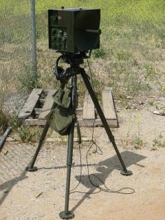
May 022006

Pictures
Specifications
General
| Personnel Detection Range (0.5m2 target) | 50 to 1500 meters |
|---|---|
| Vehicle Detection Range (10m2 target) | 50 to 3000 meters |
| Range Accuracy | ±25 meters |
| Range Resolution | 50 meters |
| Range Gate Width | 45 meters |
| Azimuth Coverage | 0 to 6400 mils (clockwise and counterclockwise) |
| Azimuth Accuracy | ±18 mils |
| Azimuth Resolution | 155 mils |
| Automatic Area Search | A 315m or 600m range depth is scanned in an azimuth range of 600, 900 or 1200 mils. |
| Elevation Coverage | +400 mils to -600 mils |
| Elevation Accuracy | ±18 mils |
Transmitting System
| Frequency Range | 9.0 to 9.5 GHz |
|---|---|
| Pulse Rate | 1800-2200 pulses per second |
| Peak Power | 100W min. |
| Pulse Width | 0.22 to 0.30μs |
| RF Power Source | Magnetron, Varian BLM-003 |
Antenna System
| Transmission Line | Section of RG-52/U waveguide equipped with a choke-type input flange |
|---|---|
| Radiating Element | Slotted waveguide |
| Reflector | Truncated parabolic, 12″ diameter |
| Antenna Gain | 24.5dB min. |
| E-plane Beamwidth (3dB point) | approx. 7° |
| H-plane Beamwidth (3dB point) | approx. 8° |
| Sidelobes | Not less than 13dB attenuation |
Receiving System
| Type | Superheterodyne |
|---|---|
| Operating Frequency | 9.0 to 9.5GHz (tunable) |
| Local Oscillator Tube Type | Klystron, Varian VA203B |
| Local Oscillator Frequency | 30MHz below magnetron frequency |
| Crystal Protection | Solid-state limiter |
| Intermediate Frequency | 30MHz ±2MHz |
| Intermediate Frequency Bandwidth | 6.3MHz ±0.6MHz at 3dB points |
| Intermediate Frequency Gain | 80dB min. |
| Intermediate Frequency Manual Gain Control | 40dB min. |
| Audio Bandwidth | 26 to 1000Hz |
| Minimum Discernible Signal (MDS) | -95dBm |
Indicating System
| Headset | Aural detection and identification |
|---|---|
| Test Meter | Visual indicator |
| Range Indicator (mechanical counter) | Range readout in meters |
| Elevation Indicator (dial) | Elevation angle readout in mils |
| Azimuth Indicator (dial) | Direct azimuth reading in mils (0-6400) |
Antenna Positioning System
| Azimuth Drive System | Sector scan motor, 2200RPM reduced through gearing to approx. 3RPM |
|---|---|
| Automatic Sector Scan Area | 300, 450 or 600 mils left and right of a predetermined position set by the sector scan ring |
| Manual Sector Scan Area | Manual scanning performed by operator from 0-6400 mils |
| Azimuth Scan Rate | 58 mils/second nominal |
| Azimuth Scan Motor | 12VDC permanent magnet gearhead motor |
| Elevation | Manual tilt, +400 to -600 mils |
Power Source
| Type | Self-contained 12V silver-zinc battery or external 12VDC source |
|---|---|
| Power | 15.7W max. at 12VDC input |


send me a picture of the wave guide output connector and I will see if I have an adapter to coax…Jay Simmons K6RIY
This picture above shows the wave guide connector. The wave guide itself is probably some common size, but the flange is a twist-lock fitting which is probably custom. The test adapter I’m looking for is intended to fit into the waveguide output at the center of the dish, in place of the normal feedhorn which is sitting on top of the unit in that picture. If and when I ever get around to playing with this radar again, I may just need to fabricate an adapter.
Now that I know what it looks like, I can search through the channel 11 obsolete microwave stuff. Jay
Thanks!
Just found this web page. Brings back memories. In 1969-1970 I repaired dozens of “Pippsy Sixes” when I was at 3rd FSR, Camp Foster, Okinawa. While I don’t have one, the test coupler your looking for is a closed waveguide section with a matching twist lock on one end, and an N connector with 1/4 wave stub inside the waveguide at the other. The N is mounted on the waveguide width, 90 degrees to the wide side. As I recall, the coupler is about 4-5 inches long.
I used an X band radar test set, TS-147, for transmitter and receiver test and adjustment. Years ago I bought a TS-147 at a swap meet for a few bucks. It worked then and probably still does. If the mixer attenuator ever quits due to loss of the silver plating on the movable quartz plate, let me know. There is a cheap way I used to fix the missing silver that worked just fine. Anyway thanks for the memories.
Richard
In 1953 the US Army had a portable ground surveillance or battlefield radar tested in Korea. They were tested in an ROK sector and almost lost due to combat. My guess it was an early version of the AN/PPS3,4,5 family line of radars.
See basic story at:
http://www.thekwe.org/memoirs/carpenter/index.htm
Any idea what this radar unit was called or designated? Or a picture?
Any help appreciated. Thank you.
I have no idea. This is the first I have heard of them. Thank you for sharing!