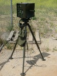

Military radio and wireline communications equipment, and related stuff.

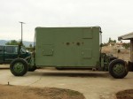
I bought this S-448 communications shelter on 11/22/2005 from another military radio and vehicle collector. I plan to use it as my primary radio room at home. It originally housed a Collins AN/TSC-60(V)1 “Communication Central” set. The interior was completely stripped of equipment when the previous owner bought it, and he installed some equipment racks, desks, drawers, etc. He also re-wired it to run from single-phase power instead of three-phase power. The shelter would have originally had a panel on the right side of the door with a whole bunch of connectors and binding posts, but that has been replaced by a blank metal panel. If I need to add any external electrical connections, that would be the obvious place to do it. Some of the ventilation panels leak, but they look like they’ll be fairly easy to repair. Overall, the shelter is in good shape, and it’ll make a really nice radio shack.
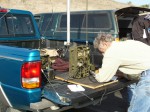
Here are some pictures that I took at my team’s site during the 2005 Military Radio Collector’s Group Field Exercise, on November 5, 2005 near Fort MacArthur in San Pedro, California. Bill Feldman N6PY and I set up in a parking lot at Friendship Park, with a nice view overlooking the ocean. We fielded a BC-1306 HF backpack transceiver, a BC-659 10m FM transceiver, and my Chinese Type 102E HF transceiver.
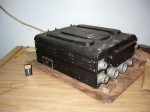
I bought this PE-101-C dynamotor through eBay in March of 2005, with plans to add it to my junk pile for potential use as a power supply for some future homebrew project. It appears to be unused WW-II surplus. It turned out to be interesting enough that I’d rather use it as part of a proper restoration of the radio system that it belonged to.
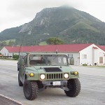
Once again, the annual meeting of the Military Radio Collector’s Group was held at the Camp San Luis Obispo NCO’s club. The meeting was held on Friday, May 5 and Saturday, May 6, 2000. Friday was mostly dedicated to informal activities and display setup, along with some radio operating events and several really fun hidden transmitter hunts using 6m FM military radio gear. Cam Ogan, WA6VVC provided a fancy little hidden transmitter for us to find, and I bet it was funny to watch all of us guys running around with big, green radios and “rug-beater” direction-finding loop antennas! The swap meet, formal presentations, and David Ragsdale’s great barbecue were on Saturday. Unfortunately, I had to cut my visit short due to some engine trouble with my HMMWV, so I missed most of the fun on Saturday this year.

This design is a solid-state replacement for ballast tube R-32 in the AM-65/GRC audio amplifier. When the AM-65 is used as a power supply for the RT-70 transceiver, R-32 regulates the RT-70’s tube filament current. The original part is described as follows in the service manual for the AM-65/GRC (TM 11-5039):
R-32 RESISTOR, thermal: current through lamp greater than .58 amp w/4.3 v measured across lamp and less than .625 amp w/9.7 v measured across lamp; designed for DC; T-9 bulb, 2 7/8″ lg o/a; intermediate octal base; Amperite type #6-4; Fed Tele & Rad part/dwg #GH-2677-2.
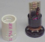
This design is a solid-state replacement for thermal relay K-1 in the AM-65/GRC audio amplifier. When the AM-65 is used as a power supply for the RT-70 transceiver, K-1 protects the filament chain by reducing the filament current if the filament voltage rises too high. This can happen when certain tube filaments burn out, and can cause a chain reaction that burns out many other tube filaments. The original part is described as follows in the service manual for the AM-65/GRC (TM 11-5039):
K-1 RELAY, thermal: SPST normally closed; cont rating 2 amp max; silver cont; single wnd heat coil, operates at 6.9 v DC w/ 1 amp cont load, release at 2 to 3.5 v, heater current 250 ma w/6.9v applied, ins; coil and cont leads terminate in octal base; 1.275″ diam x 2 7/8″ lg excluding base cont and locating pin; mts by means of octal base; operates within 10 sec; incl in type T-9 bulb w/std octal base; Raytheon #CK-118; Fed Tele & Rad part /dwg #GH-2392-12.

This page contains links to scanned images of a 1966 installation manual which describes the “correct” way to install radio set AN/GRC-106 in the M38A1 truck. Each page was scanned at 150 DPI and saved as a GIF image. This is the complete manual; the original was unbound, without any cover. The original was fairly blurry, so some pages are difficult to read.
by Buzz Harrah, KE0MS
February 15, 1999
Originally posted to the MilSurplus Mailing List
Reprinted with permission
Calling all MIL-itants,
Recently you all came to my rescue when I needed “Fatherly” advice on a BC-348 I’d found. Thanks to your info, I’ve worked a deal with only pickup yet to take place. Your pricing information especially helped the deal “gel”.
I was asked by several thru direct mail if I could gather together my info and publish it for all the other BC-348 “wannabe owners” out there, kind of as an FAQ or something. I got almost 2-dozen responses over the weekend to send it, so, (not knowing how many are on this list) I decided it’s easier to let you all get it and judge for yourself if you need it. Delete it if you don’t.

This page contains links to scanned images of a 1967 installation manual which describes the “correct” way to install radio sets AN/VRC-46, AN/VRC-53, or AN/GRC-125 in the M37 truck. Each page was scanned at 150 DPI and saved as a GIF image. This is the complete manual; the original was unbound, and consisted of two double-sided sheets followed by five foldouts, 3-hole punched and stapled together without any cover.
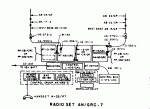
This page shows the major components of many of the US military vehicular radio sets in use during the 1950’s. Each link points to a picture which shows the major radio components, mounts, cables, antenna components, etc. that were used in the indicated radio set. These pictures were scanned from a large foldout in the back of TM 11-284: Radio Sets AN/GRC-3, -4, -5, -6, -7, and -8, dated May, 1953.
So, you just bought a TV-7 (or TV-7A, TV-7D, etc.) tube tester at a ham radio swap, and now you’re wondering how to test and align it. The alignment procedure isn’t too difficult, and a photocopy of the technical manual is available from Fair Radio Sales if you don’t already have one. If your tester is missing its tube data book, you can order a reprint from Antique Electronic Supply, as well as replacements for the shorts lamp and the fuse lamp.