Jun 071999
Radio equipment and accessories.
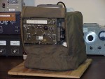
This design is a solid-state replacement for ballast tube R-32 in the AM-65/GRC audio amplifier. When the AM-65 is used as a power supply for the RT-70 transceiver, R-32 regulates the RT-70’s tube filament current. The original part is described as follows in the service manual for the AM-65/GRC (TM 11-5039):
R-32 RESISTOR, thermal: current through lamp greater than .58 amp w/4.3 v measured across lamp and less than .625 amp w/9.7 v measured across lamp; designed for DC; T-9 bulb, 2 7/8″ lg o/a; intermediate octal base; Amperite type #6-4; Fed Tele & Rad part/dwg #GH-2677-2.
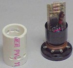
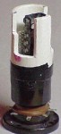
This design is a solid-state replacement for thermal relay K-1 in the AM-65/GRC audio amplifier. When the AM-65 is used as a power supply for the RT-70 transceiver, K-1 protects the filament chain by reducing the filament current if the filament voltage rises too high. This can happen when certain tube filaments burn out, and can cause a chain reaction that burns out many other tube filaments. The original part is described as follows in the service manual for the AM-65/GRC (TM 11-5039):
K-1 RELAY, thermal: SPST normally closed; cont rating 2 amp max; silver cont; single wnd heat coil, operates at 6.9 v DC w/ 1 amp cont load, release at 2 to 3.5 v, heater current 250 ma w/6.9v applied, ins; coil and cont leads terminate in octal base; 1.275″ diam x 2 7/8″ lg excluding base cont and locating pin; mts by means of octal base; operates within 10 sec; incl in type T-9 bulb w/std octal base; Raytheon #CK-118; Fed Tele & Rad part /dwg #GH-2392-12.
by Buzz Harrah, KE0MS
February 15, 1999
Originally posted to the MilSurplus Mailing List
Reprinted with permission
Calling all MIL-itants,
Recently you all came to my rescue when I needed “Fatherly” advice on a BC-348 I’d found. Thanks to your info, I’ve worked a deal with only pickup yet to take place. Your pricing information especially helped the deal “gel”.
I was asked by several thru direct mail if I could gather together my info and publish it for all the other BC-348 “wannabe owners” out there, kind of as an FAQ or something. I got almost 2-dozen responses over the weekend to send it, so, (not knowing how many are on this list) I decided it’s easier to let you all get it and judge for yourself if you need it. Delete it if you don’t.
This page shows the major components of many of the US military vehicular radio sets in use during the 1950’s. Each link points to a picture which shows the major radio components, mounts, cables, antenna components, etc. that were used in the indicated radio set. These pictures were scanned from a large foldout in the back of TM 11-284: Radio Sets AN/GRC-3, -4, -5, -6, -7, and -8, dated May, 1953.